IBM Quad Digital Trunk Telephony PCI Adapter (DTTA)
Feature Code 6312 and Feature Code 6313
Installation and User's Guide
First Edition (January 2003)
Ò International Business Machines Corporation 2003. All rights reserved.
Note to U.S. Government Users -- Documentation related to restricted rights -- Use, duplication or disclosure is subject to restrictions set forth is GSA ADP Schedule Contract with IBM Corp
| Handling Static Sensitive Devices | Page 4 |
| About This Book | Page 5 |
| ISO 9001 | Page 5 |
| Trademarks | Page 5 |
| Chapter 1. Product Description | Page 6 |
| Part Number | Page 6 |
| Chapter 2. Installation | Page 7 |
| Hardware Requirements | Page 7 |
| Software Requirements | Page 7 |
| Installing the IBM Quad Digital Trunk Telephony PCI Adapter | Page 8 |
| H.100 Connections | Page 8 |
| Synchronisation of Trunk Clocks | Page 9 |
| Jumper Installation Information | Page 9 |
| Connecting H.100 Adapters Together | Page 10 |
| Prerequisites | Page 10 |
| IBM Quad Digital Trunk Telephony PCI Adapter Internal Cabling | Page 10 |
| Connecting a DTTA Adapter to the Telephone Network | Page 11 |
| Prerequisites | Page 11 |
| Procedure | Page 11 |
| Important Notes. | Page 11 |
| Chapter 3. Problem Determination | Page 12 |
| Diagnostic Wrap Plugs | Page 12 |
| Chapter 4.Telecommunications Cables and Connectors | Page 13 |
| RJ-48C Jack Connector Socket | Page 14 |
| T1/E1 Crossover cable: RJ-48C/RJ-48C | Page 15 |
| T1/E1 Crossover cable: RJ-48C/DB15 | Page 17 |
| T1/E1 Straight - Through cable: RJ-48C/DB15 | Page 18 |
| Appendix A. Communications Statements | Page 19 |
| Federal Communications Commission (FCC) Statement | Page 19 |
| European Union (EU) Statement | Page 19 |
| International Electrotechnical Commission (IEC) Statement | Page 20 |
| Canadian Department of Communications Compliance Statement | Page 20 |
| VCCI Statement | Page 20 |
| Electromagnetic Interference (EMI) Statement - Taiwan | Page 20 |
| Radio Protection for Germany (NEEDS UPDATING) | Page 21 |
| China, EMC Statement | Page 21 |
| Telecommunications Statements | Page 22 |
| FCC Part 68 Compliance Information | Page 22 |
| Canada Telecommunications Statement | Page 23 |
| Notices for New Zealand Users (New Statement needed) | Page 23 |
_____________________________
Handling Static Sensitive Devices
Attention: Static electricity can damage this device and the system unit. To avoid
damage, keep this device in its static protective bag until you are ready to install it.
To reduce the possibility of electrostatic discharge, follow the precautions listed
below:
from the package and from your body.)
static-protective package. (If the device is an adapter, place it component-side
up.) Do not place the device on a system unit cover or on a metal table.
_______________
About This Book
This book describes the IBM Quad Digital Trunk Telephony PCI Adapter. Use this information along with the system unit documentation to help install the adapter and prerequisite software.
Terminology Note
Throughout this book, the IBM Quad Digital Trunk Telephony PCI Adapter will be used synonymously with DTTA.
ISO 9001
ISO 9001 registered quality systems were used in the development and
manufacturing of this product.
Related Information
This book refers to documentation that came with the system unit.
Trademarks
AIX, RS/6000, p-Series and IBM are registered trademarks of International Business Machines
Corporation.
Other company, product, and service names may be trademarks or service marks of
Others.
____________________________
Chapter 1. Product Description
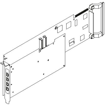
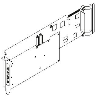
The IBM Quad Digital Trunk Telephony PCI Adapter (DTTA), Feature Code 6312, is a full-size PCI adapter that supports 32/64-bit busses at bus speeds up to 66 MHz and is compliant with PCI Local Bus Specification Revision 2.2. Feature Code 6313 is the IBM Quad Digital Trunk Telephony PCI Blind Swap Adapter. Feature Code 6313 consists of a DTTA installed in the Blind Swap Cassette (BSC). It is intended to facilitate the use of the IBM Quad Digital Trunk Telephony PCI Adapter (DTTA) in those machines that support the BSC. The DTTA assembly consists of a base and daughter card, however the Field Replaceable Unit (FRU) for FC 6312 is the total assembly. (It should not be necessary to separate the DTTA assembly at any time). FC 6313 has two FRUs; the DTTA assembly, which is same as FC 6312, and the BSC.
The DTTA is designed to be functionally equivalent to the IBM ARTIC960RxD Quad Digital Trunk PCI Adapter (DTXA) IBM Feature Code 6310.
The adapter is designed specifically to process voice data supplied by a telephony connection on a pSeries computer using Websphere Voice Response for AIX software product, providing three functions:
The adapter also has a top card H.100 interface connection, which is the industry standard for the interconnection of multiple telephony adapters in PCI systems. This interface is used to synchronise clocks when multiple adapters are installed and to support functions such as voice recognition, FAX and channel to channel connection (tromboning).
All functional code for the adapter is provided by IBM Websphere Voice Response for AIX software product and downloaded during boot-up.
The DTTA is not intended to be connected to lines that go outside the building. It does not have the surge and isolation characteristics to meet the inter building requirement . Therefore, any lines that go outside the building need to have some type of "isolation" equipment located between line coming from the outside and the DTTA. This can be a CSU or any other type of equipment that isolates the line (i.e. that which provides the surge and isolation characteristic that meet the inter building requirement).
The DTTA conforms to CCITT G703 which states:
In the United States the DTTA has an FCC Equipment Classification "XD", 'System Ports Connecting to CSU', conforming to DSX-1 interface. When the DTTA is connected to a central office switch via a T1 trunk, the connection must be made through a Channel Service Unit (CSU). The CSU protects the circuit against power surges and allows the telephony company to test the trunk.
In other countries, a CSU or equivalent device (eg. NT1, NCTE, NPD etc.) may also be needed if the DTTA is connected to a Central Office/Network Switch. A CSU or equivalent device may also be needed if the DTTA is being connected to a PBX or channel bank etc. and the distance is such that the cable loss exceeds the requirements of G703 (6dB) or the cable exits the building.
Where 75 ohm connection is required this can be achieved with an appropriate Balun such as "Black Box Balun MT242A-M or MT242A-F". This particular Balun was certified as part of the approval testing of this adapter. However, the local telecom company may specify a particular device
.
Part Number
The DTTA Field Replaceable Unit (FRU) Part Number is 00P3119.
Note: The IBM Quad Digital Trunk Telephony PCI Adapter is an EMC FCC and CISPR Class A device.
The Federal Communications Commission (FCC) classification for this product might differ from the FCC classification for the system unit. Use the classification that is highest. For example, if the FCC classification for the system unit is Class B and a Class A card is installed, the classification of the system unit would change to Class A.
_ _________________
Chapter 2. Installation
Each IBM Quad Digital Trunk Telephony PCI Adapter (DTTA) package includes the following:
Hardware Requirements
The IBM Quad Digital Trunk Telephony PCI Adapter is a universal voltage 32/64-bit PCI device capable of operating in either 33 or 66 MHz slots. It can be installed in supported RS/6000's and p-Series systems. The DTTA is not "Hot Pluggable", see Note 2. under "Installing the IBM Quad Digital Trunk Telephony PCI Adapter" . For the current list of supported systems, contact the installing IBM representative.
A maximum number of DTTA's supported by a given machine is specified by the particular system unit, please do not exceed this number. Refer to the publication "PCI Adapter Placement Reference" Form No. SA38-0538 Section " Digital Trunk PCI Adapter Considerations", for correct placement of adapters. The IBM Quad Digital Trunk Telephony PCI Adapter (Feature Code # 6312) cannot coexist with the IBM ARTIC960RxD Quad DTA (Feature Code # 6310).
The following cables are needed:
Software Requirements
The IBM Quad Digital Trunk Telephony PCI Adapter will only be supported on IBM WebSphere Voice Response for AIX Program Product version 3.1 (PTF Level XXXXXX) or higher running under AIX versions 5.X or higher.
The Device Driver and Diagnostics are only shipped with IBM WebSphere Voice Response for AIX
Installing the IBM Quad Digital Trunk Telephony PCI Adapter
The following procedure describes how to install the DTTA into the system unit. The steps may vary depending on the system unit, particularly if it is a system which supports a Blind Swap Cassette (BSC). Refer to the documentation that came with the system unit for detailed instructions on performing the following procedures:
If a single DTTA (Feature Code 6312 or 6313) was ordered with a new RS/6000 or p-Series machine and there is no intention to connect to other Scbus or H.100 adapters, then DTTA is already installed in the machine, proceed directly to "Connecting a DTTA Adapter to the Telephone Network".
If multiple DTTA's (Feature Code 6312 or 63113) were ordered with a new RS/6000 or p-Series machine and their installation will suit the customer's partitioning scheme, then proceed directly to "Connecting a DTTA Adapter to the Telephone Network".
However, if DTTA's need to be moved to suit a particular partitioning scheme OR the intent is to connect to other H.100 adapters, then follow the procedure below.
If the DTTA (Feature Code 6312 or 6313) (Single or multiple) was ordered as an addition to an existing installation, then follow the procedure below.
Note 1: Ensure that the jumper JP1 is set as described in "Jumper Installation Information" If FC 6313 was ordered and it is the third or fourth instance of FC 6313, then the BSC must be disassembled before JP1 may be moved.
Note 2: The WebSphere Voice Response for AIX software product (for which the DTTA is designed) does not support replacement of adapters whilst still running. If the RS/6000 or p-Series supports adapter replacement while the machine is still powered on (but with the adapter slot powered off using a machine utility) the WebSphere Voice Response software must be stopped before any such operation.
H.100 Connections
All DTTA, and any other H.100 adapters in an RS/6000 or p-Series must be connected together using an H.100 top-connector cable. This is to synchronise clocks on the adapters and to support functions such as voice recognition and channel-to-channel connection (tromboning). H.100 is the industry standard for connection of telephony adapters in PCI systems.
To make connection easier, install H.100 adapters in adjacent slots in the RS/6000 or p-Series system unit.
Two cables are available as feature codes, along with three cable specify codes for Feature Code 2877. (see Table 1). Order the required cable(s) to suit the application. When using multiple DTTAs in a partition, the correct Grouping Indicator must also be specified.
Table 1. H.100 Cables fo DTTA Adapter
| Feature Code | Cable |
| 2877 | 4-way H.100 |
| 4353 | 8-way H.100 |
| 9007 | 2 Slot Grouping Indicator |
| 9008 | 3 Slot Grouping Indicator |
| 9009 | 4 Slot Grouping Indicator |
Normally use cable F/C 2877 for up to 4 adapters in adjacent slots.
Cable F/C 4353 can be used when adapters are not in adjacent slots.
Synchronisation of Trunk Clocks
DTTA trunk interfaces are designed to operate in a clock-slave mode where the adapter attempts to recover the clock from the received signal and synchronises its transmit clock to this recovered received clock. If the network or PBX is not configured as a clock master, incorrect operation and clock instability may result.
For DTTA systems, unsynchronized trunk clocks can be handled by the adapter but it adjusts the internal clock in order to normalise all clocks to the internal bus using a clock slippage algorithm. This will probably not be noticeable on voice, but may result in excessive data errors if trunks are being used for other types of data, such as fax.
For this reason, it is strongly recommended that all trunk clocks be synchronised (this will probably be the case naturally with direct network connections, but channel banks may require some special attention).
Jumper Installation Information
Jumper JP1 is used to terminate each end of the H.100 chain, and should be set as follows:
If the adapter to be installed is NOT connected to either end of the
H.100 Cable (see the illustration on page 12), then set the jumper as
shown in Figure A, to the right.
If the adapter to be installed is connected to either end of the H.100
Cable (see the illustration on page 12), the jumper must be installed
as shown in Figure B, to the right.
If the adapter to be installed is the only DTTA in the
system, then set the jumper as shown in the illustration to the right.
This is the factory setting.
Connecting H.100 Adapters Together
Prerequisites
Before connecting the H.100 adapters together, note the following:
• H.100 adapters should ideally be in adjacent slots.
• For H.100 adapters, the termination jumper JP1 must be set for the adapter at each end of the chain. For details see the section " Jumper Installation Information".
IBM Quad Digital Trunk Telephony PCI Adapter Internal Cabling
Multi-drop cable assemblies are used to connect the internal busses of installed DTTA's. There are two top card cables, FC 2877 and FC 4353 along with three Grouping Indicator codes for FC 2877.
FC 2877 and FC 4353 are used to connect multiple DTTA's to each other as well as other adapters with H.100 connectors, see below. FC 2877 cable is just long enough to connect four adapters that support H.100 connectors in adjacent slots. FC 4353 can be used for more than four adapters and/or to bridge gaps between adapters.
H.100, 4-Drop Cabling: The DTTA's have H.100 top card connectors.
The following figure illustrates the internal cabling for the DTTA's with the H.100 top card connectors cabled together. Up to four DTTA's are supported and must be in adjacent slots. Refer to "Jumper Installation Information " to position the jumper on JP1 on the base card.
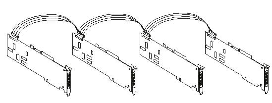
4 Drop H.100 Cable
Attention: Do not connect or handle the cable during a lightning storm.
Connecting a DTTA Adapter to the Telephone Network
Prerequisites
One to four RJ-48C telephony cables for each DTTA adapter. See Section "Cables and Connectors"
Procedure
Connect the appropriate RJ-48C cable from the telephony network to the desired port on the DTTA. Making sure that the transmit-to-network pins at one end are connected to receive-from-network pins at the other end, and vice versa. See Section " Cables and Connectors"
Note: The 4- RJ45/RJ48C ports of the DTTA adapter are numbered 1, 2, 3 and 4. These will correspond to WebSphere Voice Response for AIX trunks numbered:
Important Notes.
In the United States, when the DTTA is connected to a central office switch via a T1 trunk, the connection must be made through a Channel Service Unit (CSU). The CSU protects the circuit against power surges and allows the telephony company to test the trunk.
In other countries, a CSU or equivalent device (e.g.. NT1, NCTE, NPD etc.) may be needed if connecting to a Central Office/Network Switch. A CSU or equivalent device may also be needed if connecting the DTTA to a PBX or channel bank etc. and the distance is such that the cable loss exceeds the requirements of G703 (6dB) or the cable exits the building.
Where 75 ohm connection is required this can be achieved with an appropriate Balun such as "Black Box Balun MT242A-M or MT242A-F". This particular Balun was certified as part of the approval testing of this adapter however, the local telecom company may specify a particular device.
_____________________________
Chapter 3. Problem Determination
The diagnostics for the DTTA are ONLY shipped as part of the Websphere Voice Response for AIX (WVR/AIX) software product. You will need to install WVR/AIX before you are able to test the DTTA adapters.
Installing DTTA Device Drivers
The diagnostic program for DTTA is 'rpqtest' which can be found in /usr/lpp/devices.iop_rpq after WVR/AIX has been installed and then the DTTA drivers installed fropm the WVR/AIX file system (WVR/AIX will tell you how to do this during installation).
DTTA device drivers should be installed using 'smitty' in the standard way.
Checking Installed Adapters
After installing the DTTA drivers, it is necessary to do a power-cycle, reboot or run the command 'cfgmgr' (as root) to get the DTTA devices recognised and configured.
To check that the DTTA device(s) have been correctly configured, perform the following command ...
lsdev - C | grep rpq
AIX will display two lines for each DTTA adapter installed, one for the adapter itself (rpqioX) and the other for it's device driver (ddrpqioX).
The following is an example of what you should see if four adapters are installed:
rpqio0 Available 1H-08 Quad Digital Trunk Telephony PCI Adapter (ID=13310008)
rpqio1 Available 1V-08 Quad Digital Trunk Telephony PCI Adapter (ID=13310008)
rpqio2 Available 1Z-08 Quad Digital Trunk Telephony PCI Adapter (ID=13310008)
rpqio3 Available 1D-08 Quad Digital Trunk Telephony PCI Adapter (ID=13310008)
ddrpqio0 Available 1H-08-00 Digital Telephony Device Driver
ddrpqio1 Available 1V-08-00 Digital Telephony Device Driver
ddrpqio2 Available 1Z-08-00 Digital Telephony Device Driver
ddrpqio3 Available 1D-08-00 Digital Telephony Device Driver
If the adapter and device driver have been correctly configured, both should be shown as 'Available' (the 'Defined' state indicates that the adapter has not been detected or configured, or the device driver has not configured correctly).
The third column in the above display (e.g. 1H-08) indicates the slot position for the adapter. Refer to the Users Manual for the system unit for details of how the information in this field maps to a physical slot.
Running diagnostics (no wrap plugs)
Hardware diagnostics can be run on the DTTA but only when WVR is not active as otherwise WVR will experience unexpected failures. Therefore, before attempting to run diagnostics on the DTTA, bring WVR down (from the GIU or using the command DT_shotdown).
To run DTTA hardware diagnostics, proceed as follows ..
1) login to AIX
2) become root
3) enter the following commands to set up the diagnostic test environment
export RPQPATH=/usr/lpp/devices.iop_rpq
export PATH=$PATH:/usr/lpp/devices.iop_rpq/bin
4) To test an adapter once, enter
rpqtest <X> 99 -I
Where <X> is the card number corresponding to rpqio<X>
You will be asked to confirm the PMC ID (should be 0xa1331) and then the test will proceed through the various tests. If the diagnostics do not find any problems with the adapter, they will end with the message 'Tests Completed Successfully.
5) To test a single adapter continously until stopped, add the -C option to the above
Note that the above test do not require wrap plugs to be installed on the telephony (RJ45) interface.
You should repeat the above command for each adapter in the system to ensure that the hardware is working.
If any test fails, the most likely cause is a faulty adapter which should be replaced.
Running diagnostics (with wrap plugs)
To test the adapter with installed wrap plugs and the full set of diagnostics, 4 X "RJ48 plug cable wrap" IBM part number 87H3588 are required. These should be temporarily plugged into the adapter back plate for all four trunks in place of the T1/E1 cable.
Then follow the above procedure for running the diagnostics but with no parameters on 'rpqtest' and follow the instructions to test the adapter(s) with external wrap plugs installed.
If any test fails, first check that the wrap plugs are correctly seated and try re-running the diagnostics. If a failure persists, change the adapter card.
Adapter LEDs
The DTTA has a single LED on the bottom of the card. This will stay orange while the system is being booted and while diagnostics are being run on the DTTA. After installing the DTTA device drivers and after running diagnostics, this LED should turn green.
If the LED stays orange and the system has been fully booted, the card may be faulty (check for installed adapters and device drivers as described above and then run diagnostics to make sure that the card is good).
Unlike its predecessor (DTXA), DTTA does NOT have LEDs per T1/E1 trunk to show the state of the individual trunks. Instead, a utility is provided with WVR/AIX (DTXA_alarms) which will show the trunk enebaled and alarm state for both DTXA and DTTA.
Chapter 4. Telecommunications Cables and Connectors
This section provides guidance on network cables for the attachment of the DTTA to the T1 or E1 Digital trunk.
The DTTA is configured as DTE, therefore the cable type needed will depend on the configuration of the equipment the DTTA is being connected to :-
Connecting to equipment configured as DTE.......Use crossover cable.
Connecting to equipment configured as DTE...... Use Straight through cable
Common types are:-
RJ-48C/RJ-48C Crossover Cable. ( Transmit and Receive pairs cross over in the cable)
RJ-48C/RJ-48C Straight Through. ( Transmit and Receive pairs carried through cable)
RJ-48C/DB15 Crossover Cable. ( Transmit and Receive pairs cross over in the cable)
RJ-48C/DB15 Straight Through. ( Transmit and Receive pairs carried through cable)
RJ-48C/ Bare ends (For MDF IDC must have 22/24 AWG solid core)
IBM do not provide these cables, they can be obtained from commercial cable suppliers in a variety of specifications and lengths to suit the particular installation. It is recommended that the cable and connectors used, meet the following specification:-
1) The DTTA conforms to CCITT G703 which states:
Therefore joining cables to achieve required length should be avoided as each joint introduces loss and is a potential point of failure.
2) The cable should be ideally 22/24 AWG gauge with an impedance of 100 ohm (T1) or 120 ohm (E1), and the send and receive pairs should be individually shielded twisted pairs with the shielding connected to the connector shield. The cable should have an outer PVC jacket and be shielded using either foil and drain wire (US style) or foil and braid (European style). This shielding is particularly important in a NEBS-compliant Telco service provider or similar environment where extensive cable securing or tying may lead to bi-polar violations due to EMC interference between cables.
3) To conform with good electrical practice, cable routing should not be close to wiring that carries mains voltage or high currents, in order to minimise any noise induced in the telephony cabling.
4) Cables should be clearly labelled at each end such that they can be easily identified from end to end.
5) Please note T1 cable is not the same as CAT5 cable, even though they both have 100 ohms impedance. Always use T1.
See the following pages for more detail
RJ-48C Jack Connector Socket
The following illustration shows an RJ-48 jack connector. The Table lists the pin assignments for the T1 and E1 electrical interfaces.
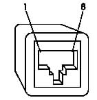
RJ-48C Connector Pin Assignments
| Signal Name | I/O | RJ-48 Connector |
| TX1 (ring) TX2 (tip) FGND RX1 (ring) RX2 (tip) |
O O --- I I |
04 05 06,07,08,03 01 02 |
| FGND | --- | Housing |

Port 4
Port 3
Port 2
Port 1
Yellow LED
DTTA Adapter Backplate
T1/E1 Crossover cable: RJ-48C/RJ-48C
Install the RJ-48C/RJ48C crossover cable when the interface the DTTA is being connected to an interface that transmits on pins 1 and 2 and receives on pins 4 and 5
RJ-48C/RJ-48C crossover cable
Connects to DTTA Connects to T1/E1 Source
Note: Ground/Shield connections are not shown in this diagram
T1/E1 Straight-Through cable: RJ-48C/RJ-48C
Install the RJ-48C/RJ48C straight - through cable when the interface the DTTA is being connected to an interface that transmits on pins 4 and 5 and receives on pins 1 and 2
RJ-48C/RJ-48C straight - through cable
Connects to DTTA Connects to T1/E1 Source
Note: Ground/Shield connections are not shown in this diagram
T1/E1 Crossover cable: RJ-48C/DB15
Before installing the RJ-48C/DB15 crossover cable check that T1/E1 source that is being connected to the DTTA transmits on pins 1 and 9 and receives on pins 3 and 11.
RJ-48C/DB15 crossover cable
Connect to T1/E1 Source Connect to DTTA
Note: Ground/Shield connections are not shown in this diagram
T1/E1 Straight - Through cable: RJ-48C/DB15
Before installing the RJ-48C/DB15 crossover cable check that T1/E1 source that is being connected to the DTTA transmits on pins 3 and 11 and receives on pins 1 and 9.
RJ-48C/DB15 straight - through cable

Connect to T1/E1 Source Connect to DTTA
Note: Ground/Shield connections are not shown in this diagram
____________________________________
Appendix A. Communications Statements
The following statement applies to this product. The statement for other products
intended for use with this product appears in their accompanying documentation.
Federal Communications Commission (FCC) Statement
Note: This equipment has been tested and found to comply with the limits for a
Class A digital device, pursuant to Part 15 of the FCC Rules. These limits are
designed to provide reasonable protection against harmful interference when the
equipment is operated in a commercial environment. This equipment generates,
uses, and can radiate radio frequency energy and, if not installed and used in
accordance with the instruction manual, may cause harmful interference to radio
communications. Operation of this equipment in a residential area is likely to cause
harmful interference in which case the user will be required to correct the
interference at his own expense.
Properly shielded and grounded cables and connectors must be used in order to
meet FCC emission limits. Neither the provider nor the manufacturer are responsible
for any radio or television interference caused by using other than recommended
cables and connectors or by unauthorised changes or modifications to this
equipment. Unauthorised changes or modifications could void the user's authority to
operate the equipment.
This device complies with Part 15 of the FCC Rules. Operation is subject to the
following two conditions: (1) this device may not cause harmful interference, and (2)
this device must accept any interference received, including interference that may
cause undesired operation.
European Union (EU) Statement

Hereby, the manufacturer, declares that the IBM Quad Digital Trunk Telephony PCI Adapter is in compliance with the essential requirements and other relevant provisions of Directive 1999/5/EC.
The full Declaration of Conformity is available from IBM's Homologation and Type Approval Department in LaGaude.
This product has been tested and found to comply with the limits for Class A
Information Technology Equipment according to CISPR 22 / European Standard EN55022. The limits for Class A equipment were derived for commercial and industrial environments to provide reasonable protection against interference with licensed communication equipment.
Warning: This is a Class A product. In a domestic environment this product may
cause radio interference in which case the user may be required to take adequate
measures.
International Electrotechnical Commission (IEC) Statement
This product has been designed and built to comply with IEC Standard 950.
Avis de conformité aux normes du ministère des Communications du Canada
Cet appareil numérique de la classe A est conform a la norme NMB-003.
Canadian Department of Communications Compliance Statement
This Class A digital apparatus complies with ICES-003.
VCCI Statement

The following is a summary of the VCCI Japanese statement in the box above.
This is a Class A product based on the standard of the Voluntary Control Council for
Interference by Information Technology Equipment (VCCI). If this equipment is used
in a domestic environment, radio disturbance may arise. When such trouble occurs,
the user may be required to take corrective actions.
Electromagnetic Interference (EMI) Statement - Taiwan
.
The following is a summary of the EMI Taiwan statement above
Warning: This is a Class A product. In a domestic environment this product may
cause radio interference in which case the user will be required to take adequate
Measures.
Radio Protection for Germany (NEEDS UPDATING)
Dieses Gerät ist berechtigt in Übereinstimmung mit Dem deutschen EMVG vom
9.Nov.92 das EG–Konformitätszeichen zu führen.
Der Aussteller der Konformitätserklärung ist die IBM Germany.
Dieses Gerät erfüllt die Bedingungen der EN 55022 Klasse A. Für diese von
Geräten gilt folgende Bestimmung nach dem EMVG:
Geräte dürfen an Orten, für die sie nicht ausreichend entstört sind, nur mit
besonderer Genehmigung des Bundesministers für Post und Telekommunikation
oder des Bundesamtes für Post und Telekommunikation betrieben werden. Die
Genehmigung wird erteilt, wenn keine elektromagnetischen Störungen zu erwarten
sind.
(Auszug aus dem EMVG vom 9.Nov.92, Para.3, Abs.4)
Hinweis
Dieses Genehmigungsverfahren ist von der Deutschen Bundespost noch nicht
veröffentlicht worden.
China, EMC Statement
_____________________________
Telecommunications Statements
FCC Part 68 Compliance Information
The IBM Quad Digital Trunk Telephony PCI Adapter complies with Part 68 of the FCC rules (TIA/EIA-TSB-168).
The label located on the back side of the adapter contains, among other information, the FCC registration number for this equipment. If requested, provide this information to the local telephone company.
The IBM Quad Digital Trunk Telephony PCI Adapter is designed to be connected to the telephone network or premises wiring using a compatible modular RJ-48 plug and cable, which are Part 68 compliant.
If the IBM Quad Digital Trunk Telephony PCI Adapter causes harm to the telephone network, the
telephone company may discontinue your service temporarily. If possible, they will
notify you in advance. But if advance notice is not practical, you will be notified as
soon as possible. You will be advised of your right to file a complaint with the FCC.
Your telephone company may make changes in its facilities, equipment, operations,
or procedures that could affect the proper operation of your equipment. If they do,
you will be given advance notice so as to give you an opportunity to maintain
uninterrupted service.
If trouble is experienced with this equipment, for repair or warranty information, in the
United States, call IBM at 1-800-IBM-SERV. In Canada, call IBM at 1-800-465-6600.
No repairs can be performed by the customer.
Canada Telecommunications Statement
NOTICE: This equipment meets the applicable Industry Canada Terminal Equipment Technical Specifications. This is confirmed by the registration number. The abbreviation, IC, before the registration number signifies that registration was performed based on a Declaration of Conformity indicating that Industry Canada technical specifications were met. It does not imply that Industry Canada approved the equipment.
AVIS : Le présent matériel est conforme aux spécifications techniques d'Industrie Canada applicables au matériel terminal. Cette conformité est confirmée par le numéro d'enregistrement. Le sigle IC, placé devant le numéro d'enregistrement, signifie que l'enregistrement s'est effectué conformément à une déclaration de conformité et indique que les spécifications techniques d'Industrie Canada ont été respectées. Il n'implique pas qu'Industrie Canada a approuvé le matériel.
Australian Telecommunications Statement (New Statement Needed)
A mandatory statement may be issued by Austel when Type Approval is granted.
Notices for New Zealand Users (New Statement needed)
A mandatory statement may be issued by Telecom NZ when Type Approval is granted.