
Quick Beginnings
These instructions describe how to create new profiles within a new
configuration. If you are modifying an existing configuration, you may
need to delete some profiles before you can verify the configuration.
Begin to configure your DB2 Connect system with the following steps:
- Double-click on the Communications Server icon.
- Double-click on the Communications Manager Setup icon.
- On the Communications Server Setup panel, click on the Setup
push button.
- On the Open Configuration panel:
- Specify the name of an existing configuration file if you have one, or
provide a name for a new file to be created.
- Click on the OK push button to proceed to the Communications
Server Configuration Definition panel.
- The Configuration Definition panel opens.
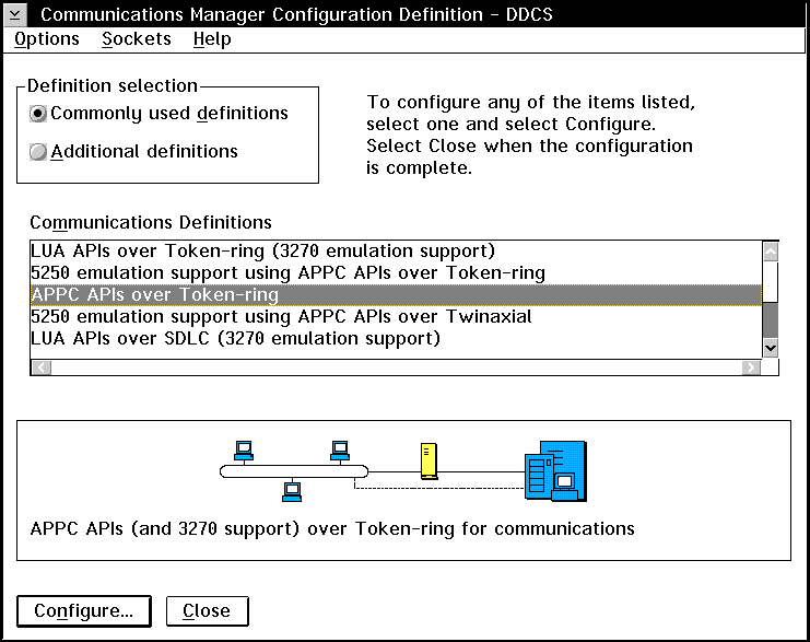
- Select the Commonly used definitions radio button.
- In the Communications Definitions window, select the protocol that you
want to use. These examples use APPC APIs over
Token-Ring.
- Click on the Configure push button to proceed.
If this is a new configuration file, the next panel displayed will be the
APPC APIs over Token-Ring panel. Otherwise the next panel displayed
will be the Communications Server Profile List panel.
- The APPC APIs over Token-Ring panel opens.
- Enter your values for:
- Network ID (9)
- Local node name (10)
- Click on the End node push button that your network
administrator advises you to use.

|
You can select either the End node - to a network node server
radio button or the End node - no network node server radio
button. A network node server is used when many users are routed
through the same connection. The example here presumes no network node
server is used.
|
- Click on the Advanced push button. The Communication
Manager Profile List window opens.
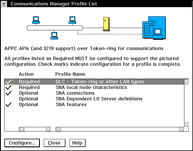
Subsequent steps begin from this panel. You will return to this
panel when each step is complete.
From the Communications Server Profile List panel, prepare a LAN DLC
profile as follows:
- Select DLC - Token ring or other LAN
types->Configure.
- Enter your value for Network ID or C&SM LAN
ID. (9)
- Check that the other values are appropriate for your environment.
The values in the example are default values.
- Click on OK to return to the Communications Server Profile List
panel.
Update SNA Local Node Characteristics as follows:
- On the Communications Server Profile List panel, select SNA local
node characteristics->Configure. The Local Node
Characteristic panel opens.
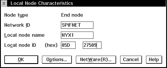
- Enter your value for Network ID (9).
- The Local node name was probably set when Communications Server
was installed. If you are not sure, consult your local network
administrator.
- Enter your value for Local node ID (hex) (13) and
(14).

|
The first part should be filled in for you already when you display the
profile. You only need to complete the second part.
|
- Click on the Options push button. The Local Node Options
panel opens.
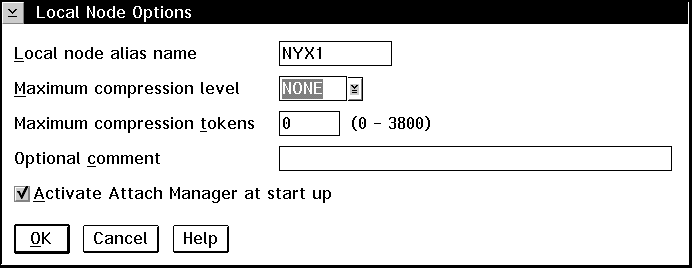
- Verify that the Activate Attach Manager at startup check box is
selected.
- Click on OK to return to the Local Node Characteristics
panel.
- Click on OK to return to the Communications Server Profile List
panel.
Prepare the SNA connection profiles as follows:
- From the Communications Server Profile List panel, select SNA
Connections->Configure.
- On the Connections List panel for Partner Type, select either
the To peer node radio button (normally used for OS/400
connections), or the To host radio button (normally used for
OS/390, MVS, VSE, and VM connections), and click on the Create push
button.
- The Adapter List window opens.
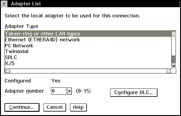
- Select the Token-ring, or other LAN types adapter type, and
specify the same adapter number that you specified in the DLC
profile.
- Click on the Continue push button to proceed to the Connection
to a Peer Node panel or the Connection to a Host panel.
The Connection to a Peer Node or Connection to a Host Node windows
opens.
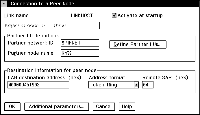
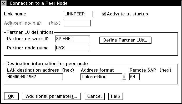
At the Connection to a Peer Node panel or the Connection to Host
panel:
- Specify the Link name value that you wrote in item (7)
of the worksheet.
- On the Connection to Host panel, select Additional parameters
push button and change the Local PU name field to your value for
(10).
- Change the node ID field to your values for (13) and
(14).
- Change LAN destination address field to your value for
(8)(16).
- Change Partner network ID field to your value for
(1).
- Change Partner node name field to your value for
(4).
- Select Define Partner LUs push button on either the Connection
to a Peer Node panel or the Connection to Host panel to proceed.
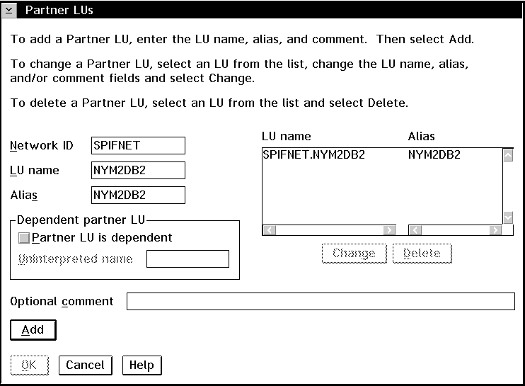
Create a Partner LUs Profile as follows:
- Enter your value for Network ID (3).
- Enter your value for LU name and Alias (use
(2) for both).
- Click on the Add push button to add the partner LU profile to
the connection profile.
- Click on OK to return to the previous panel.
- On the Connection to Host panel, click on the Additional
Parameters push button. The Partner LU window opens
If you have selected to configure connections to a host, the following
window appears.
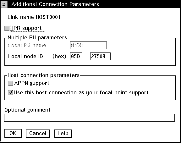
- Verify that the Multiple PU Parameters fields are filled
in. This value is the Local Node ID in hex, items (13) and
(14) in the worksheet.
- Local node ID
- 05D 27509
- Click on OK to return to the Connection to a Host panel.
- Click on OK to return to the Connections List panel.
- Click on the Close push button to return to the Communications
Server Profile List panel.
On the Communications Server Profile List panel, select SNA
features->Configure. Subsequent steps begin
from the SNA Features List panel that appears, as follows:
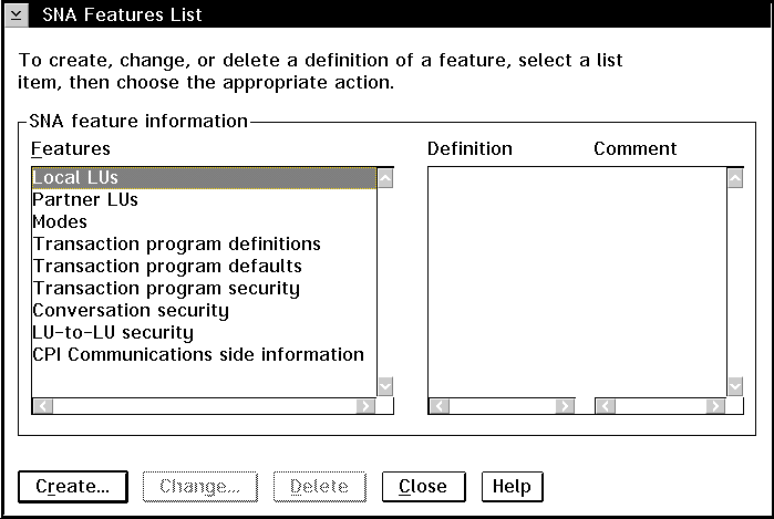
If the DB2 Connect workstation is defined as an independent LU, prepare
a Local LU Profile as follows. In most cases, a VTAM administrator on
OS/390, MVS, VSE, or VM would define an independent LU for DB2 Connect.
For OS/400, the control point would normally be used instead of an independent
LU.
- On the SNA Features List panel, click on Local
LUs->Create.
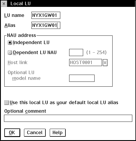
- Enter your value for LU name (11).
- Enter your value for alias (12).
- For the NAU address box, select the Independent LU
radio button.
- Click on OK to return to the SNA Features List panel.
- In order to use this local LU when the DB2 Connect workstation starts the
APPC connection, select the Use this local LU as your default local LU
alias check box. By default, all APPC connections that are
started from this DB2 Connect workstation will use this local LU.
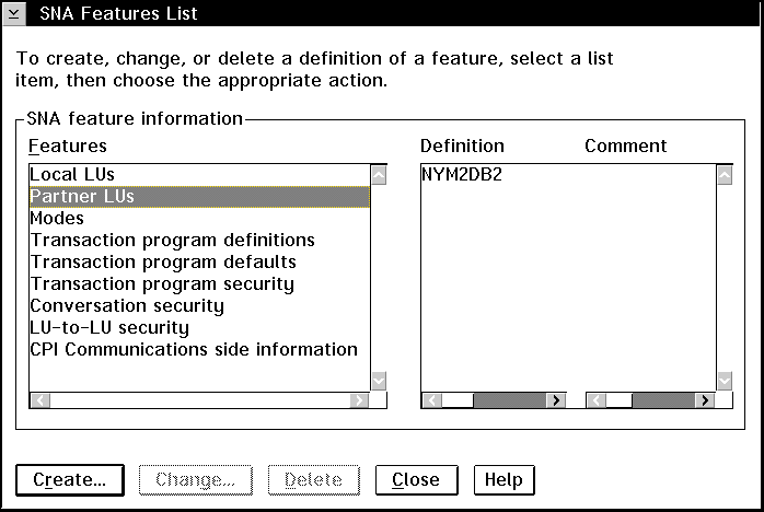
The partner LU profile was configured in a previous step. To
verify, select the Partner LU Profile option from the SNA Features
List panel to see if a partner LU is defined.
From the SNA Features List panel, prepare a Mode Definition as
follows:
- Select Modes->Create.
- Define your mode profile as follows:
- Enter your value for mode name (15). It must also
match item (6).
- On the other lines, you can either specify values that match the mode
profile defined on your DRDA server systems, or tune the parameters.
- Click on OK to finish the creation of the mode and to return to
the SNA Features List panel.
On the SNA Features List panel, select CPI Communications Side
Information->Create. The CPI Communications Side
Information opens.
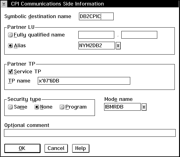
Complete the CPI Communications Side Information panel as follows:
- Enter your value for Symbolic destination name
(16).
- Select the Alias radio button. Click on the
Alias drop down box to view a list of all defined aliases and
choose the alias that corresponds to item (12).
- In the Partner TP box, specify the remote Transaction Program
(TP) name (17).
Select the None radio button as the Security
type.

|
This does not mean that you will have no security, you will specify the
security type later when you update the DB2 directories.
|
- Enter your value for the Mode name field (6).
- Click on OK to save the CPI side information profile and return
to the SNA Features List panel.
- Click on Close to return to the Communications Server Profile
List panel.
[ Top of Page | Previous Page | Next Page | Table of Contents | Index ]
[ DB2 List of Books |
Search the DB2 Books ]


